
Introduction
In modern motor control systems, accurate rotor position information is essential for achieving precise motion, stable speed regulation and reliable closed-loop control. Unlike incremental sensors that only provide relative movement information, an absolute encoder can determine the rotor’s position immediately after the system is powered on.
Magnetic Encoder Absolute Position technology uses a combination of a permanent magnet ring, Hall sensors and signal-processing algorithms to convert mechanical rotation into an electrical position signal. The system can determine the shaft angle without requiring the motor to return to a reference position first.
This makes magnetic encoders particularly useful in servo motors, robotics, industrial automation, electric vehicles and other applications where reliable position feedback is required.
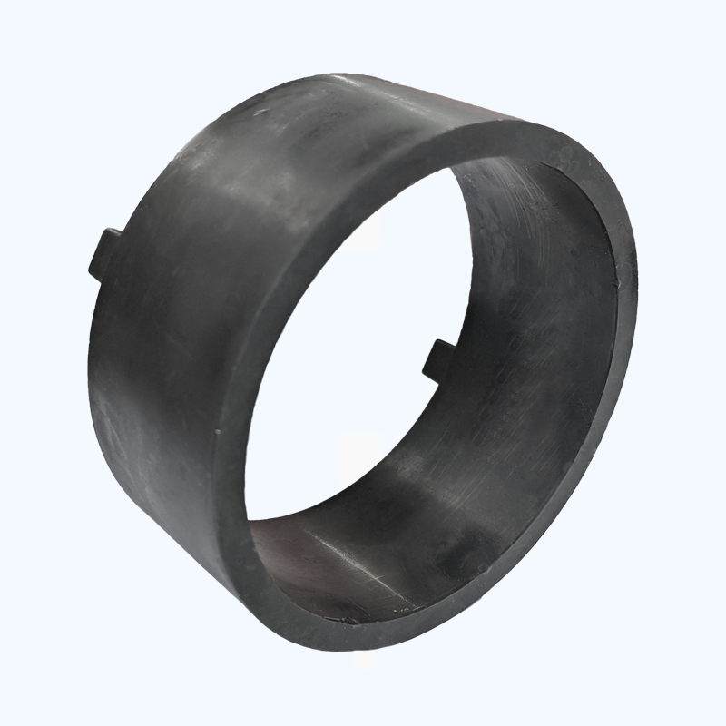
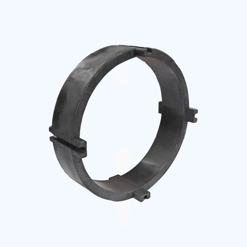
What Is a Magnetic Encoder?
A magnetic encoder is a non-contact position sensing device that detects changes in a magnetic field to determine the rotational position of a shaft.
The basic system normally consists of three main parts:
- Permanent magnet ring
- Hall sensing element
- Signal processing circuit
The permanent magnet ring rotates together with the motor shaft, while the Hall sensor remains fixed relative to the motor housing.
As the shaft rotates, the magnetic field detected by the sensor changes continuously. The sensor converts these magnetic-field changes into electrical signals, which are then processed by the encoder electronics to calculate the rotor angle.
How Does Magnetic Encoder Absolute Position Reading Work?
The process of obtaining absolute position can be divided into three stages: magnetic-field sensing, signal conditioning and angle calculation.
Magnetic Field Generation by the Permanent Magnet Ring
The rotor side of the encoder normally uses a permanent magnet ring with a specific magnetization pattern.
For many high-precision applications, the ring is radially magnetized with alternating N and S poles around its circumference.
When the magnetic ring rotates, the direction and intensity of the magnetic field at the Hall sensor change according to the mechanical position of the rotor.
This changing magnetic field provides the fundamental position information required by the encoder.
Hall Sensor Detection
Hall sensors detect the changing magnetic field generated by the rotating magnetic ring.
A typical system may use two Hall sensing elements positioned to detect different magnetic-field components. Another approach is to use an integrated 3D Hall sensor capable of detecting multiple magnetic-field directions.
The detected magnetic components can be represented as Hx and Hy.
As the magnetic ring rotates, these components vary approximately according to sine and cosine functions.
The sensor electronics then convert the magnetic-field information into two analog signals:
- Vsin
- Vcos
These signals have an electrical phase difference of approximately 90 degrees.
Why Sine and Cosine Signals Are Important
The combination of sine and cosine signals allows the encoder to determine the angular position continuously.
If the signals are represented ideally as:
Vsin = A × sinθ
Vcos = A × cosθ
where A represents signal amplitude and θ represents the rotor angle, the relationship between the two signals contains the angular position information.
Because the two signals are mathematically related, the system can determine the rotor angle even though neither signal alone provides complete position information.
How Is the Rotor Angle Calculated?
After obtaining Vsin and Vcos, the encoder needs to calculate the corresponding mechanical angle.
A basic mathematical relationship can be expressed as:
θ = arctan(Vsin / Vcos)
However, a conventional arctangent function cannot distinguish all four quadrants of a complete rotation. Its output range is limited, making it unsuitable for directly determining a full 360-degree mechanical position.
Why ATAN2 Is Used in Magnetic Encoders
Practical encoder systems therefore use the ATAN2 function.
ATAN2 evaluates both Vsin and Vcos simultaneously and determines the correct quadrant according to the sign of each input signal.
This allows the system to calculate a continuous angular position across the complete rotation:
0°–360°
or
0–2π radians
The calculated angle corresponds directly to the mechanical position of the motor shaft.
This is one of the key steps that allows a magnetic encoder to provide absolute position information.
What Is the CORDIC Algorithm?
In embedded motor-control systems, continuously calculating trigonometric functions can require significant processing resources.
To improve calculation efficiency, many dedicated encoder ICs use the CORDIC (Coordinate Rotation Digital Computer) algorithm.
Advantages of CORDIC Processing
CORDIC can efficiently calculate functions such as arctangent through repeated shift and addition operations.
This means the encoder can perform angle calculations without relying heavily on a floating-point arithmetic unit.
The approach is particularly useful for:
- Embedded motor controllers
- Microcontroller-based systems
- Servo drives
- Compact encoder ICs
- Real-time motion-control systems
By integrating CORDIC processing into the encoder, manufacturers can achieve fast position calculations while keeping hardware requirements relatively low.
What Causes Magnetic Encoder Position Errors?
Although the principle is relatively straightforward, real-world magnetic encoder signals are never perfectly ideal.
Several sources of error can cause the calculated position to deviate from the actual mechanical angle.
Amplitude Mismatch
The amplitudes of Vsin and Vcos may not be identical because of differences in Hall sensor sensitivity, magnetic-field distribution or electronic circuit characteristics.
This amplitude imbalance can introduce angular errors.
DC Offset
Temperature changes, electronic component tolerances and circuit drift can introduce DC offsets into the sine and cosine signals.
Instead of being centered around zero, the signals may shift upward or downward.
If these offsets are not corrected, the calculated rotor position will be inaccurate.
Quadrature Phase Error
Ideally, Vsin and Vcos should maintain a 90-degree phase relationship.
However, mechanical mounting tolerances, sensor positioning errors and magnetic ring installation deviations can cause phase displacement.
Even a relatively small phase error can affect position accuracy in precision applications.
How Are Magnetic Encoder Errors Compensated?
To improve the accuracy of Magnetic Encoder Absolute Position systems, manufacturers typically perform calibration during factory testing or system initialization.
During one complete rotation, the system records important signal characteristics, including:
- Maximum signal value
- Minimum signal value
- Zero-crossing points
- Signal amplitude
- Phase relationship
The collected information is then used to establish an error compensation model.
Amplitude Normalization
The controller adjusts the amplitudes of Vsin and Vcos so that the two signals have a more consistent relationship.
Offset Removal
The DC offset of each signal is measured and removed during digital signal processing.
Phase Correction
The system identifies the deviation from the ideal 90-degree phase relationship and applies correction coefficients to reduce the resulting angular error.
After compensation, the processed signals are sent to the angle calculation module.
Why Absolute Position Accuracy Matters in Motor Control
Accurate absolute position information directly affects motor performance.
A precise position signal allows the controller to improve:
- Motor commutation
- Speed regulation
- Position control
- Torque control
- Servo response
- Startup behavior
For robotics and precision automation, even small angular errors can accumulate into noticeable positioning deviations.
This is why magnetic encoder design involves not only the magnetic ring itself, but also sensor positioning, signal quality and digital compensation.
Applications of Magnetic Encoder Absolute Position Technology
Magnetic encoder systems are increasingly used where reliable position feedback is required.
Servo Motors
Servo motors require accurate rotor position information for closed-loop position and speed control.
Magnetic encoders provide a compact and durable feedback solution.
Industrial Robots
Robotic joints operate through repeated acceleration, deceleration and precise positioning.
The non-contact nature of magnetic sensing makes it suitable for demanding industrial environments.
CNC Machine Tools
CNC equipment requires accurate rotational feedback to maintain machining precision.
Magnetic encoder systems can provide reliable position information even in environments exposed to vibration, dust and contaminants.
Electric Vehicle Systems
Electric power steering and other automotive motor systems require reliable rotor position feedback.
Magnetic sensing technology offers good resistance to environmental conditions while maintaining compact dimensions.
Magnetic Encoder vs Optical Encoder
Magnetic and optical encoders use different sensing principles.
Optical encoders rely on light and coded discs, while magnetic encoders detect changes in magnetic fields.
Magnetic encoders offer several practical advantages:
- Non-contact operation
- Good vibration resistance
- Strong contamination resistance
- Compact structure
- Reliable operation in demanding environments
For applications exposed to dust, oil, vibration or mechanical shock, magnetic sensing can provide a useful alternative to optical position sensing.
How to Improve Magnetic Encoder Position Accuracy
Achieving high accuracy requires optimization of the complete sensing system rather than focusing on only one component.
Key factors include:
Magnetic Ring Design
The number of magnetic poles, magnetization pattern, material and dimensional accuracy all influence the magnetic field detected by the Hall sensor.
Sensor Position
The Hall sensor must be positioned accurately relative to the magnetic ring.
Small installation deviations can introduce phase errors.
Signal Quality
Stable and well-balanced sine and cosine signals provide a better foundation for accurate angle calculation.
Digital Compensation
Calibration and compensation algorithms can correct amplitude, offset and phase errors that cannot be completely eliminated during mechanical manufacturing.
Why Choose Highkos for Magnetic Encoder Rings?
Highkos specializes in customized magnetic components for motor position sensing and precision motion-control applications.
Our capabilities include:
- Magnetic encoder rings
- Hall sensing magnetic rings
- Multi-pole magnetic rings
- Permanent ferrite magnetic rings
- Injection molded magnetic components
- Customized magnetization solutions
- OEM and ODM manufacturing
Highkos works with motor and encoder manufacturers to develop magnetic rings according to specific dimensions, pole configurations, magnetic properties and application requirements.
Frequently Asked Questions
What is magnetic encoder absolute position?
Magnetic encoder absolute position refers to the ability of a magnetic encoder to determine the motor shaft’s actual angular position immediately after startup without requiring a reference movement.
How does a magnetic encoder determine rotor position?
A permanent magnet ring generates a changing magnetic field as it rotates. Hall sensors detect this field and generate sine and cosine signals, which are processed to calculate the rotor angle.
Why are sine and cosine signals used?
The two signals have a 90-degree phase relationship. Together, they provide sufficient information to determine the rotor angle across a complete 360-degree rotation.
What is ATAN2 used for?
ATAN2 calculates the angle from two signal inputs while identifying the correct quadrant. It allows the encoder to determine a continuous position across a complete rotation.
Can magnetic encoder accuracy be improved through calibration?
Yes. Amplitude mismatch, DC offset and phase errors can be measured and compensated through calibration and digital signal processing.
What magnetic ring is used in a magnetic encoder?
The encoder typically uses a specially magnetized permanent magnetic ring. The material, pole number, dimensions and magnetization pattern depend on the encoder design and required position accuracy.
Conclusion
Magnetic encoder technology provides an effective way to convert mechanical rotor movement into accurate electrical position information. Through the coordinated operation of a permanent magnet ring, Hall sensors, sine-cosine signal processing, ATAN2 calculation and error compensation, the system can determine rotor position immediately after startup.
For modern servo motors, robotics, CNC equipment and automotive applications, Magnetic Encoder Absolute Position technology offers an attractive combination of accuracy, reliability and environmental resistance. As motor control continues moving toward higher precision and smarter operation, properly designed magnetic encoder rings will remain an important component of advanced position-sensing systems.