
Introduction to Ferrite Magnetic Rings for EMI Suppression
Ferrite Magnetic Rings are widely used as electromagnetic interference (EMI) suppression components in power and signal cable systems. In this application, the magnetic ring works as a common-mode choke, helping reduce unwanted high-frequency noise while allowing normal operating current and signals to pass through.
As electronic equipment becomes increasingly interconnected, EMI can affect smart-home devices, industrial controllers, LED power supplies, cameras, sensors and communication equipment. Properly selected Ferrite Magnetic Rings can provide a compact and economical solution for controlling common-mode interference.
The effectiveness of a magnetic ring depends on several factors, including ferrite material, operating frequency, ring dimensions, cable diameter and the number of winding turns.
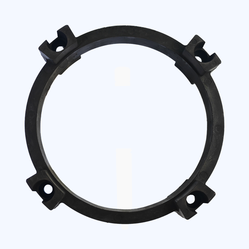
What Are Ferrite Magnetic Rings?
Ferrite Magnetic Rings are ring-shaped soft magnetic components generally made from ferrite materials with frequency-dependent impedance characteristics.
When a cable passes through the magnetic ring, the ring interacts with common-mode high-frequency currents traveling along the conductor. At the target interference frequencies, the ferrite material presents increased impedance to unwanted noise.
This allows the component to attenuate high-frequency interference without significantly affecting the normal low-frequency operating current.
Depending on the application, Ferrite Magnetic Rings can be installed around:
- Power cables
- USB cables
- Signal cables
- Communication cables
- Motor cables
- Adapter cables
- Sensor wiring
How Ferrite Magnetic Rings Suppress EMI
Common-Mode Noise Suppression
The primary function of Ferrite Magnetic Rings in cable applications is common-mode noise suppression.
Common-mode interference travels in the same direction along multiple conductors relative to a common reference. When these high-frequency currents pass through the ferrite material, the ring creates a frequency-dependent impedance.
At higher frequencies, this impedance can significantly reduce the propagation of unwanted noise.
The absorbed electromagnetic energy is primarily converted into heat within the magnetic material.
Low-Frequency Current Transmission
A properly selected Ferrite Magnetic Ring does not function like a simple resistor that blocks all current.
Instead, its impedance changes with frequency.
Normal low-frequency operating current can continue to flow through the cable, while higher-frequency interference experiences significantly greater impedance.
This frequency-selective behavior makes ferrite rings useful for protecting electronic systems without interrupting their normal operation.
Problems Addressed by Ferrite Magnetic Rings
Interference Between Smart-Home Devices
Modern homes may contain many electronic devices connected to the same power network.
Variable-frequency air conditioners, LED dimming power supplies, smart gateways and other switching equipment can generate conducted high-frequency noise.
This interference may travel through shared power circuits and affect:
- Smart speakers
- IP cameras
- Smart gateways
- Touch switches
- Sensors
- Communication equipment
Installing Ferrite Magnetic Rings at appropriate cable locations can help reduce the transmission of unwanted common-mode noise.
Transient Switching Interference
Motor starting and stopping, relay switching and other rapid electrical transitions can generate transient pulses.
These disturbances may cause:
- False touch-switch triggering
- Sensor data fluctuations
- Communication errors
- Unstable electronic control
- Unexpected device behavior
A correctly selected ferrite ring can provide additional high-frequency impedance and help suppress these disturbances.
Ferrite Magnetic Rings in Smart-Home Equipment
Smart-home products are increasingly sensitive to electromagnetic interference because many devices combine switching power supplies, wireless communication and digital control circuits in compact enclosures.
Factory-Installed Magnetic Rings
During manufacturing, Ferrite Magnetic Rings can be installed near the input or output cable of a device.
Common locations include:
- Power-adapter cable roots
- PCB power-input terminals
- Communication cable interfaces
- USB power cables
- Internal wiring harnesses
Placing the ferrite component close to the interference source or sensitive circuit can improve the overall EMI-control strategy.
Clip-On Ferrite Magnetic Rings
For existing installations, clip-on ferrite rings provide a convenient retrofit solution.
Users can install a clip-on component around an interference-prone cable without modifying the internal circuit.
Typical applications include:
- IP camera power cables
- USB cables for smart gateways
- Router power cables
- Audio equipment cables
- Sensor cables
This approach is particularly useful when the original equipment has already been installed.
Choosing the Right Ferrite Magnetic Ring
The performance of Ferrite Magnetic Rings depends heavily on proper material and dimensional selection.
Using a ferrite ring simply because it fits the cable does not guarantee effective EMI suppression.
Ferrite Material Selection
Different ferrite materials provide different frequency characteristics.
Mn-Zn ferrite is generally suitable for lower-frequency EMI applications, commonly including interference below approximately 1 MHz.
Ni-Zn ferrite is generally more suitable for higher-frequency interference, particularly applications above approximately 1 MHz.
The actual operating frequency range should always be verified against the material’s impedance characteristics.
Ring Inner Diameter
The inner diameter of the Ferrite Magnetic Ring should be selected according to the outer diameter of the cable.
A smaller effective gap between the cable and ferrite core can generally provide better coupling.
However, the ring must still allow practical installation without damaging or excessively bending the cable.
Magnetic Ring Dimensions
The size of the ferrite core influences its impedance and magnetic characteristics.
Larger magnetic cross-sectional area can provide different impedance and saturation characteristics compared with smaller cores.
Therefore, manufacturers should evaluate:
- Outer diameter
- Inner diameter
- Ring thickness
- Magnetic path length
- Cable diameter
- Target frequency
rather than selecting a ring based solely on physical appearance.
The Influence of Winding Turns
The number of cable turns through a Ferrite Magnetic Ring is another important parameter.
One Turn
Passing a cable through the ring once creates a basic magnetic suppression structure.
This configuration is often suitable when the cable diameter or installation space limits the number of turns.
Multiple Turns
Increasing the number of turns can significantly increase the impedance of the magnetic structure at certain frequency ranges.
This can be particularly useful when stronger suppression is required at relatively lower frequencies.
However, adding turns also changes the parasitic capacitance and frequency response of the system.
Therefore, more turns are not automatically better.
The optimum number of turns should be determined according to the target interference spectrum.
Ferrite Magnetic Rings for Variable-Frequency Equipment
Variable-frequency drives and inverter-based equipment generate high-frequency switching components due to rapid voltage and current transitions.
Examples include:
- Variable-frequency air conditioners
- BLDC motor controllers
- Inverter power supplies
- LED dimming systems
- Industrial motor drives
These switching signals can propagate through power cables and potentially interfere with nearby electronic devices.
Ferrite Magnetic Rings can be incorporated into cable-based EMI suppression strategies to increase high-frequency impedance and reduce common-mode noise.
Ferrite Magnetic Rings for IP Cameras
IP cameras often operate alongside switching power supplies, network communication circuits and other electronic systems.
When the camera and other devices share a power loop, conducted interference can potentially affect system stability.
Installing a Ferrite Magnetic Ring around the camera’s power cable can provide an additional layer of high-frequency noise suppression.
For retrofit applications, clip-on ferrite components are especially convenient because installation normally does not require opening the camera housing.
Ferrite Magnetic Rings for Smart Gateways
Smart gateways often use USB or low-voltage DC power cables.
Because these devices process wireless and digital communication signals, excessive conducted noise can sometimes affect system performance.
A ferrite ring installed near the gateway-side power cable can help increase impedance to high-frequency common-mode noise.
The appropriate material and dimensions should be selected according to the actual interference frequency.
Ferrite Magnetic Rings for LED Power Supplies
LED dimming systems frequently use switching power electronics.
Rapid switching transitions can produce conducted and radiated electromagnetic interference.
A properly selected Ferrite Magnetic Ring can be integrated into the power cable or input wiring to help reduce high-frequency common-mode noise.
The effectiveness depends on the frequency spectrum generated by the particular LED driver.
Ferrite Magnetic Rings vs Permanent Magnet Rings
It is important to distinguish EMI suppression ferrite rings from permanent-magnet rotor rings.
Although both are commonly called magnetic rings, they perform completely different functions.
Ferrite Magnetic Rings for EMI Suppression
These rings normally use soft magnetic ferrite materials.
Their purpose is to:
- Increase high-frequency impedance
- Suppress common-mode noise
- Reduce conducted EMI
- Improve electromagnetic compatibility
They do not provide the permanent magnetic field required to generate motor torque.
Permanent Magnet Magnetic Rings
Permanent-magnet rings are used as rotor excitation components in motors.
They generate a stable magnetic field and interact with the stator field to produce electromagnetic torque.
The materials and design principles are therefore completely different from those of EMI suppression ferrite rings.
How to Optimize Ferrite Magnetic Ring Performance
For a successful EMI suppression design, three factors should be evaluated together.
Match the Material to the Frequency
First determine the dominant interference frequency.
Then select an appropriate ferrite material based on its impedance-frequency characteristics.
Match the Ring to the Cable
The inner diameter should be reasonably matched to the cable diameter.
Avoid selecting a core that is unnecessarily large when a closer-fitting option is available.
Optimize the Number of Turns
Increasing the number of turns can increase impedance in certain frequency ranges.
However, the frequency response changes as turns increase, so testing should be performed to determine the most effective configuration.
Why Choose Highkos for Ferrite Magnetic Rings?
Highkos provides customized magnetic component solutions for electronics, motors, automotive applications and industrial equipment.
Its magnetic component capabilities include:
- Ferrite Magnetic Rings
- EMI suppression magnetic components
- Customized ferrite cores
- Magnetic rings for cable applications
- Motor magnetic components
- Injection-molded magnetic components
- Bonded magnetic components
- OEM and ODM manufacturing
For different EMI applications, material grade, core dimensions and operating frequency should be evaluated together.
Highkos can support customized magnetic ring development according to cable size, target frequency and application requirements.
Frequently Asked Questions
What are Ferrite Magnetic Rings used for?
Ferrite Magnetic Rings are commonly used to suppress high-frequency common-mode electromagnetic interference on power and signal cables.
Do Ferrite Magnetic Rings block normal current?
They are designed to provide frequency-dependent impedance. Normal low-frequency operating current can pass through while high-frequency noise experiences greater impedance.
Which ferrite is better for EMI suppression, Mn-Zn or Ni-Zn?
Mn-Zn ferrite is generally suitable for lower-frequency applications, while Ni-Zn ferrite is commonly used for higher-frequency interference. The final choice should be based on the actual frequency spectrum.
Does increasing cable turns improve EMI suppression?
Additional turns can increase impedance at certain frequencies, particularly in lower-frequency ranges. However, excessive turns can alter the frequency response, so the optimum configuration should be tested.
Where should a ferrite ring be installed?
Typical positions include power-adapter cable roots, PCB input terminals, IP camera power cables and USB power cables for smart gateways. Placement should be determined according to the location of the interference source and sensitive circuit.
Conclusion
Ferrite Magnetic Rings provide a practical method for controlling common-mode electromagnetic interference in modern electronic equipment.
Their effectiveness is closely related to ferrite material, operating frequency, core dimensions, cable diameter and winding configuration. Mn-Zn and Ni-Zn materials cover different frequency ranges, while ring size and cable turns can be optimized according to the target suppression requirements.
For smart-home devices, variable-frequency equipment, LED power supplies, IP cameras and industrial electronics, properly selected Ferrite Magnetic Rings can help reduce conducted high-frequency noise and improve overall electromagnetic compatibility.