
Magnetization Technology for Magnetic Rings is an important process in the manufacturing of permanent magnetic components. In industrial production, magnetization is also commonly called magnet charging. The process uses a strong external magnetic field to align the magnetic domains inside a permanent magnet blank.
After the external magnetic field is removed, the magnetic material retains remanent magnetization. The final magnetic field distribution depends on the material, charging direction, fixture structure, pole arrangement, magnetic circuit, and process parameters.
For motor rotors, magnetic encoders, magnetic couplings, sensors, and other precision components, selecting the appropriate Magnetization Technology for Magnetic Rings is essential for achieving the required magnetic field pattern.
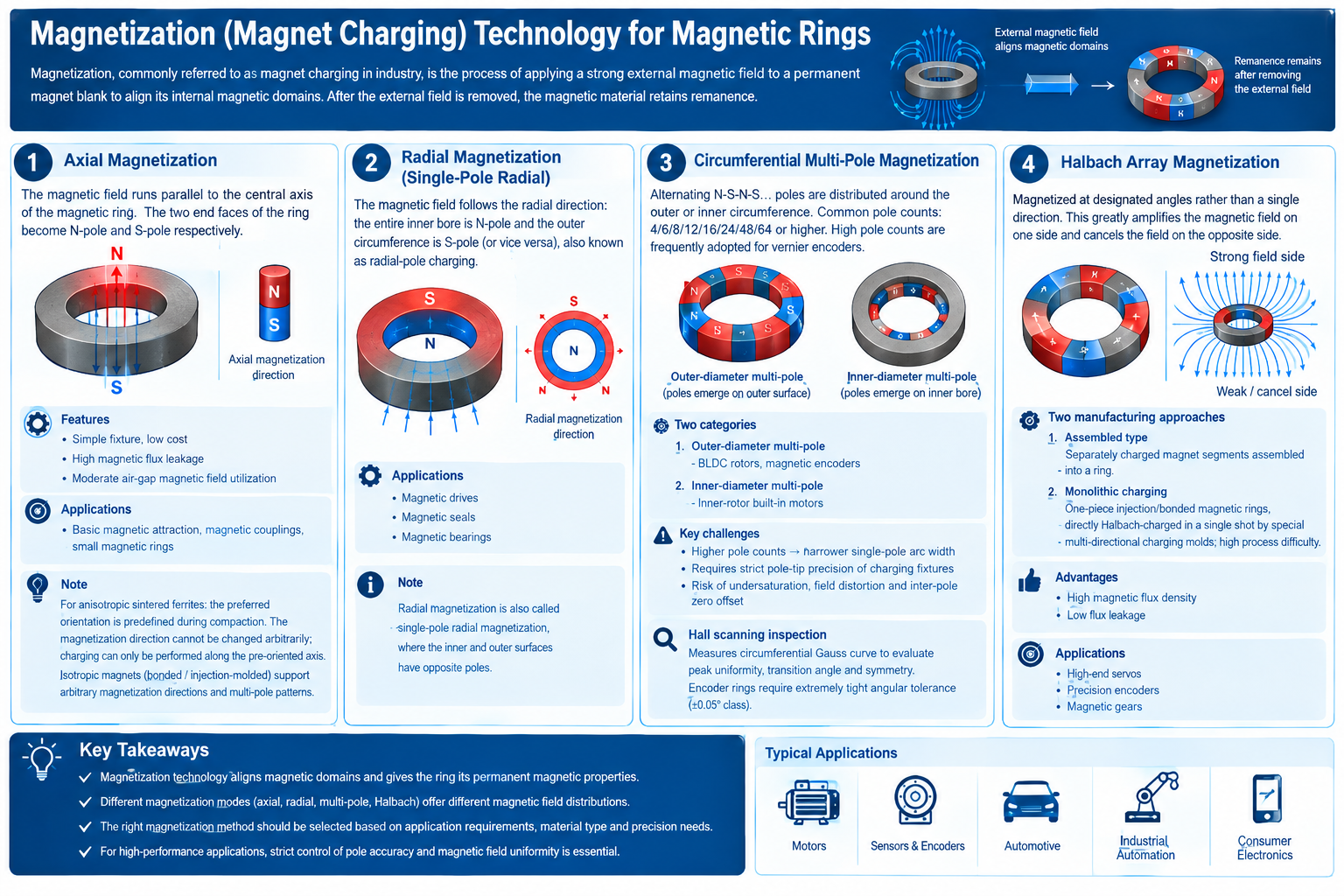
Understanding Magnetization Technology for Magnetic Rings
The basic principle behind Magnetization Technology for Magnetic Rings is the application of a sufficiently strong external magnetic field to a permanent magnet material.
Before charging, the magnetic domains inside the material are not necessarily aligned in the required direction. The external magnetic field provides the force needed to establish the desired magnetic orientation.
Once the charging field is removed, the material retains part of this magnetization as remanence.
The charging process therefore determines how the magnetic poles appear on the finished ring.
Depending on the application, a ring can be magnetized in several ways, including:
- Axial magnetization
- Radial magnetization
- Circumferential multi-pole magnetization
- Halbach array magnetization
Each method produces a different magnetic field distribution and is suitable for different mechanical and electronic applications.
Axial Magnetization in Magnetic Rings
Axial magnetization is one of the simplest forms of Magnetization Technology for Magnetic Rings.
In an axial configuration, the magnetic field used for charging is parallel to the central axis of the ring. After magnetization, one end face becomes the north pole and the opposite end face becomes the south pole.
This creates a relatively straightforward two-pole magnetic structure.
Features of Axial Magnetization
The main characteristics include:
- Simple charging fixture
- Relatively low tooling cost
- Straightforward magnetic circuit
- Simple pole arrangement
- Suitable for basic magnetic applications
One limitation is that the magnetic flux may leak significantly outside the intended magnetic path. As a result, air-gap magnetic field utilization may be lower than that of more specialized magnetic configurations.
Applications of Axial Magnetic Rings
Axially magnetized rings can be used in:
- Basic magnetic attraction
- Magnetic couplings
- Small magnetic assemblies
- Simple magnetic sensing structures
- Compact permanent-magnet components
For anisotropic sintered ferrite materials, the preferred orientation is established during the compaction process. This means the magnetization direction cannot normally be selected arbitrarily after manufacturing.
The charging fixture must therefore be designed to apply the magnetic field along the appropriate orientation axis.
Radial Magnetization for Magnetic Rings
Radial magnetization is another important approach in Magnetization Technology for Magnetic Rings.
Instead of applying the magnetic field parallel to the central axis, the charging field follows the radial direction of the ring.
In a single-pole radial configuration, the entire inner bore can form one magnetic pole while the outer circumference forms the opposite pole. The polarity can also be reversed depending on the design.
Applications of Radial Magnetization
Radially magnetized rings are useful when the magnetic field needs to be concentrated along the radial direction.
Typical applications include:
- Magnetic drives
- Magnetic seals
- Magnetic bearings
- Rotary magnetic mechanisms
- Specialized magnetic couplings
The charging fixture for radial magnetization is more specialized than a simple axial fixture because the magnetic circuit must generate the required radial field distribution.
Circumferential Multi-Pole Magnetization
Circumferential multi-pole magnetization is one of the most widely used forms of Magnetization Technology for Magnetic Rings for motors and magnetic encoders.
Instead of creating only one north pole and one south pole, multiple alternating magnetic poles are distributed around the circumference.
A typical pattern is:
N-S-N-S-N-S-N-S
Common pole counts include 4, 6, 8, 12, 16, 24, 48, and 64 poles. Higher pole counts may also be used in specialized encoder applications.
The final pole pattern is determined by the requirements of the motor, encoder, sensor, and magnetic circuit.
Outer-Diameter Multi-Pole Magnetization
In an outer-diameter multi-pole ring, the magnetic poles emerge from the outside surface.
This configuration is frequently used for:
- BLDC motor rotors
- Magnetic encoder rings
- Position sensing systems
- Rotary feedback components
The outer magnetic field interacts with sensors or other magnetic structures positioned around the circumference.
Inner-Diameter Multi-Pole Magnetization
In an inner-diameter multi-pole configuration, the magnetic poles emerge from the internal bore of the ring.
This arrangement can be applied to:
- Inner-rotor motors
- Compact motor assemblies
- Internal magnetic sensing systems
- Specialized rotary mechanisms
The choice between outer and inner pole arrangements depends on the mechanical structure and the required magnetic interaction.
High-Pole-Count Magnetization Challenges
As the number of poles increases, each individual magnetic pole becomes narrower. This makes Magnetization Technology for Magnetic Rings increasingly demanding in terms of fixture precision and magnetic circuit design.
Several problems can occur during high-pole-count charging.
Pole-Tip Undersaturation
If the magnetic field generated by the charging fixture is insufficient, the pole tips may not reach the desired magnetic state.
Undersaturation can result in lower peak magnetic flux and inconsistent signal output.
Magnetic Field Distortion
An unsuitable charging fixture or magnetic circuit may cause the magnetic field to deviate from the intended pole pattern.
Field distortion can affect motor performance, sensor signals, and encoder accuracy.
Inter-Pole Transition Error
The angular position of each magnetic pole transition needs to be controlled carefully.
If the transition points are not evenly distributed, the resulting magnetic waveform may contain angular errors or asymmetry.
For precision encoder rings, these errors can become especially important because the magnetic pattern directly contributes to position information.
Hall Scanning Inspection
Hall scanning is an important quality-control method associated with precision Magnetization Technology for Magnetic Rings.
During inspection, a Hall sensor moves around the circumference of the magnetic ring and records the magnetic field at different angular positions.
The resulting Gauss curve can be used to evaluate the consistency of the magnetic pattern.
Peak Field Uniformity
The peak magnetic field of each pole can be compared with the other poles.
Large differences between adjacent poles may indicate variations in material, magnetization, fixture alignment, or magnetic circuit performance.
Pole Transition Angle
The angular position where the magnetic field changes from one pole to another is also important.
For encoder applications, accurate transition angles help ensure that the electrical output corresponds correctly to the mechanical position.
Magnetic Symmetry
A high-quality multi-pole ring should maintain a consistent magnetic pattern around its circumference.
Hall scanning can identify:
- Uneven pole strength
- Angular displacement
- Field distortion
- Pole asymmetry
- Abnormal transition positions
For high-precision encoder rings, tight angular tolerances may be required, making magnetic scanning an important inspection step.
Material Considerations in Magnetization Technology for Magnetic Rings
Material selection has a direct influence on Magnetization Technology for Magnetic Rings.
Different permanent magnetic materials have different magnetic characteristics, orientation requirements, and charging conditions.
Anisotropic Sintered Ferrite
Anisotropic sintered ferrite has a predefined preferred orientation established during compaction.
Because the magnetic grains are oriented during production, the final magnetization direction is generally constrained by this orientation.
The charging fixture must therefore apply the magnetic field along the appropriate axis.
This requirement needs to be considered during both material manufacturing and final magnetization.
Isotropic Bonded and Injection-Molded Magnets
Isotropic bonded and injection-molded magnetic materials generally provide greater flexibility in magnetization design.
They can support different magnetization directions and customized multi-pole patterns.
This flexibility is useful for complex magnetic rings used in:
- BLDC motors
- Magnetic encoders
- Sensors
- Actuators
- Compact magnetic drives
For these applications, the material and charging process can be developed together to obtain the required magnetic field distribution.
Halbach Magnetization for Magnetic Rings
Halbach magnetization is an advanced form of Magnetization Technology for Magnetic Rings.
Instead of magnetizing the entire ring in one uniform direction, different sections are magnetized at specific angles.
The resulting magnetic field can be reinforced on one side while being significantly reduced on the opposite side.
This directional field distribution can improve magnetic flux utilization in certain designs.
Advantages of Halbach Magnetization
The main potential advantages include:
- High useful magnetic flux density
- Reduced magnetic flux leakage
- More directional magnetic field
- Better utilization of available magnetic material
- Compact magnetic system design
Halbach configurations are particularly interesting for high-performance servos, precision encoders, magnetic gears, and specialized motor systems.
Two Manufacturing Approaches for Halbach Rings
There are two common approaches within Magnetization Technology for Magnetic Rings when producing Halbach structures.
Assembled Halbach Rings
Individual magnetic segments are separately magnetized in different directions and then assembled into a complete ring.
This method provides flexibility in magnetic design, but the assembly process requires accurate positioning of every segment.
Small angular or positional errors between segments can influence the final magnetic field distribution.
Monolithic Halbach Magnetization
A one-piece bonded or injection-molded magnetic ring can be directly charged using a specially designed multi-directional magnetization fixture.
This eliminates the need to assemble individual magnetized segments.
However, the charging fixture and magnetic circuit are considerably more complicated.
Precise control of the magnetic field direction is necessary to achieve the desired Halbach pattern.
Magnetization Technology for Magnetic Rings in Motor Applications
Motor rotors are an important application area for Magnetization Technology for Magnetic Rings.
In a permanent-magnet motor or BLDC motor, the magnetic pole arrangement of the rotor needs to correspond to the motor’s electromagnetic design.
A multi-pole magnetic ring can provide alternating north and south poles around the rotor circumference.
The number of poles, magnetic field strength, pole width, and angular position can influence the interaction between the rotor and stator.
Consistent magnetization is therefore important for maintaining predictable motor characteristics.
Magnetization Technology for Magnetic Rings in Encoder Applications
Magnetic encoder rings require particularly accurate pole positioning.
A multi-pole ring generates a sequence of magnetic transitions as it rotates. A Hall sensor or other magnetic sensing element detects these changes and converts them into electrical signals.
The accuracy of the final encoder depends partly on the consistency of the magnetic pattern.
Important parameters include:
- Pole count
- Peak magnetic field
- Pole-to-pole consistency
- Transition angle
- Magnetic symmetry
- Angular error
- Sensor-to-ring air gap
As pole counts increase, the charging process and inspection requirements become more demanding.
Choosing the Right Magnetization Method
The appropriate Magnetization Technology for Magnetic Rings depends on the intended application and magnetic field requirements.
| Magnetization Method | Magnetic Pattern | Typical Applications |
|---|---|---|
| Axial | Two axial poles | Magnetic attraction, couplings |
| Radial | Inner and outer radial poles | Seals, bearings, magnetic drives |
| Outer multi-pole | Alternating outer poles | BLDC rotors, encoders |
| Inner multi-pole | Alternating inner poles | Inner-rotor motors |
| Halbach | Directional segmented field | Servos, precision encoders, magnetic gears |
The selection process should also consider material type, ring geometry, operating air gap, required magnetic flux density, pole count, production volume, and inspection requirements.
Process Control for Magnetization Technology for Magnetic Rings
A reliable charging process requires more than a high magnetic field.
The charging fixture must generate the correct field distribution, while the ring must be accurately positioned within the magnetic circuit.
Important process factors include:
- Charging field strength
- Charging pulse duration
- Fixture geometry
- Ring positioning
- Pole spacing
- Magnetic circuit design
- Material characteristics
- Temperature
- Inspection method
For high-volume manufacturing, process consistency is especially important because even small variations can affect the magnetic waveform of finished components.
Conclusion
Magnetization Technology for Magnetic Rings determines the direction and distribution of magnetic poles in a finished permanent magnetic ring.
Axial magnetization provides a simple two-pole structure, while radial magnetization creates a radial magnetic field. Circumferential multi-pole magnetization is widely used for BLDC motor rotors and magnetic encoders, while Halbach magnetization offers a more advanced approach for directional magnetic flux control.
Material characteristics must also be considered. Anisotropic sintered ferrites require charging along their predefined orientation, while isotropic bonded and injection-molded magnetic materials provide greater flexibility for customized pole patterns.
For precision magnetic rings, successful charging depends on the combined control of material, fixture design, magnetic circuit, pole geometry, charging conditions, and inspection accuracy. A well-designed Magnetization Technology for Magnetic Rings process can help produce consistent magnetic field distributions for motors, encoders, sensors, and other advanced magnetic systems.